Screen Edge Calculations

Ok - I've searched the forum and API Methods - and can't find a solution to this obviously well known and easy problem...

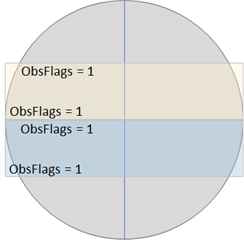
For any given row on a display screen or field... what is the obscurity offset/skew from the left and right of center?

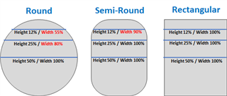
For rectangular screens, that's easy: always zero offset.

For round screens, I can calculate the Perpendicular Bisector Chord length, using some fun math (if that is really the only way to figure this out), based on the percentage from the center. Surely there is an easier way a simple API method that returns the actual width at a given row?

But for a semi-round, I'm not sure how to determine the edge of the screen for any particular row. Any ideas on a general solution. For example, maybe all semi-round displays have a corner curvature with a particular property such that a formula describes the amount of obscurity offset?

The values in RED are just illustrations... not actuals.

The ACTUAL width at LINE "Y" of a round screen with max width (aka: diameter) W is:  Width = 2 * SQRT( WY - Y^2)

And a more powerful formula is based on percentages. If you are on line X% down, then the width in percent is: W% = 2 * SQRT (X% - X%^2)

  • I'm pretty sure there is no guaranteed way to know the width of any given row on the screen.  This is something that would probably need to be computed for each device (or device group) and have special code.  Luckily there aren't  too many partial round layouts.

    And that's for apps where you have access to the whole screen.  If you were talking DF's, things can even get more confusing with the obscurity flags and possible combinations.  Not sure there is any definitive way to know for sure there.  I haven't played with it, but what are the obscurity flags for the two left DF's on the F6 in the 2nd and 3rd row when it's configured for 6 fields?

  • what are the obscurity flags for the two left DF's on the F6 in the 2nd and 3rd row when it's configured for 6 fields?

    Field 2 will have left and top, field 4 will have left and bottom. Even if the documentation isn't updated for F6 yet https://developer.garmin.com/connect-iq/user-experience-guide/appendices#appendixc:datafieldlayoutsanddimensions combined with the simulator Data Fields Layout a good way to figure out the obscurity flags.

  • I get obscurity "flags". But the obvious desired and unbelievably missing function is:

    getLineWidth(x)

    Where X is your current row or line.

    Think about how powerful that would be and how much simpler placing text and objects on the screen, particularly when data fields (and therefore, line 0) can be in many places within a screen. What a shame. So now I have to create all kind of logic to guess the data field position (F6 can have up to 8), and code math formulas to figure out the actual visible edge coordinates for every possible data field for every possible device. Insane really. When that method above would make code so damn easy and device-independent.

  • Agree.  When I read your first comment, I was thinking this would just be useful for drawing boarders, or graphics right along the edge.  But this would be really handy to figure out text placement in partially obscured fields.

    And combined with the obscurity fields, you could easily figure out that the left edge is the one that is tapered and right edge is vertical, for example.

  • This is what I mean... certainly more than 1 pixel. Both of these have obscurity flag = 1. I think this is not a bug, but the proper flags. left is obscured. the other sides are not. The issue is we can't tell only by looking at the flags. And being in a field we have no idea if the field is in the top or bottom half.

  • Yea, this is what I thought.  The obscurity flags aren't 100% decisive in this case.  I do think this is better than Left/Top and Left/Bottom since you wouldn't want to treat them the same as the bottom and top fields. 

  • I agree that it would really be useful with helper functions to create a more dynamic code for UI. 

    The way I have interpreted the use of obscurity flags for a DF is to look at the corners. And with that I would say that top and left is correct for the left yellow field and bottom left is correct for the blue. I might be wrong but if we only would get left it would be really hard to do a proper placement content in the fields.

    If I test a 6 field layout on a F6X Pro in the simulator I get 7 which is valid for the first (top) field and no else.

    Remember that there is a bug, onLayout is only called once but it should be called six times and if it follows the order used in the documentation for describing the fields it should return
    7 (left top right),
    3 (left top),
    6 (top right),
    9 (left bottom),
    12 (bottom right),
    13 (left bottom right) 

  • Yeah maybe the 1 flag is a bug. I do call onLayout() from onUpdate() and that solved the bug where width and height were only called once. So the bug in obscurity flags is in addition to the onLayout bug.

  • Ok, so I moved back to the 3.1.2 SDK (where onLayout is called correctly) for this with a 6 field layout on an f6, and print obscurity in each call to onLayout.  Here's what I see:

    obs=7 left,right,top
    obs=1 left
    obs=4 right
    obs=1 left
    obs=4 right
    obs=13 left,right,bottom

    The values from adding this to onLayout in the complex DF template:

    System.println("obs="+obscurityFlags);

    Obscurity is defined by what's "rounded", not the corners or the flat parts that aren't the full width..

  • Obscurity is defined by what's "rounded", not the corners or the flat parts that arent the full width..

    Thanks for explaining! It would have been a lot easier to understand if the simulator worked. I will change to 3.1.2 for testing and simulation and use the latest for building.