RINEX Application

The device allows for RINEX logging. Why does a consumer Outdoor Recreation device have this feature?

I've spent a few hours studying this, and it looks like a consumer can buy some specialized software to process the output, but why spend the money?

There are some free governmental processing sites like OPUS, GAPS and AUSPOS, but they seem to want multi-band data, and I believe the 66i only receives L1 data.

There is a Garmin Support Article which mentions RTKLIB, but it works in a Windows environment, and I don't.

How does the typical consumer involved with outdoor recreation actually use this functionality?

  • Understood.   I have made such efforts in the past when i knew less then i do now.  I might persue this at some point, but it's not my top priority.  

  • Here’s a 9-hour test I've just done comparing an L1 CSRS-PPP (blue) result to an L1 only RTKLIB (yellow) differential correction result for the same file to show the atmospheric effects. The static results are the large dots.

    In this case for the RTKLIB differential processing my local reference station baseline was 14.8km and a lot closer than the sparser network stations used by CSRS_PPP and you can see the atmospheric effects on the L1 only in the kinematic plots.

    The benefit of differential to a nearby reference station is that over short distances the atmospheric effects are the same and tend to cancel out.

    The static result accuracy to the known test point (red cross) for CSRS-PPP is 0.97m (3.2’) and for the RTKLIB differential result 0.30m (1’)

    If RTKLIB was enabled to differentially post processes other bands (say L5 in the case of 66sr) and/or additional constellations against the local reference station, the results are generally much better. Refer plots in previous posts.


    Additional notes:
    Because CSRS-PPP processed L1 only and has no calibration knowledge of Garmin receivers or antennas it provided a Float solution (not a fixed ambiguity resolved solution). CSRS-PPP also rejected around half of the recorded positions.

    To keep the comparison as close to apples to apples as possible, RTKLIB was set to process a float only result.

    That said, I’m still finding lots of quirks when attempting a fixed result from the 66i. Processing often results in incorrect ambiguity resolution and the results can jump around more or less wavelengths of 19cm and the results can look very noisy and spiky all over. Float results tend to be much smoother and concentrated in kinematic, and more accurate the static positions.

    The fixed test point used is known within a few mm in GDA2020 datum. And the differential results from RTKLIB were also reported in GDA2020 as it's the datum of the reference stations calibrated coordinates provided in the RINEX file.

    The CSRS_PPP ITRF results were therefore adjusted to GDA2020 for the comparison.

    Our GDA2020 is currently 20.7cm NE of ITRF (and our previous GDA94 datum is now around 1.7m NE) and both are increasing. If the CSRS-PPP ITRF to GDA2020 adjustment was not done, simply plotting the reported coordinates would incorrectly show at an additional 20.7cm to the SW (lower left) for an even greater error.

    You would have to look into your own local datum for your actual differences to ITRF. For differential correction in RTKLIB many providers including US NGS provide calibrated local datum coordinates in the RINEX file so if this is the case RTKLIB can do this systemically for you if you select the Base Station setting to be “Rinex Header Position”.

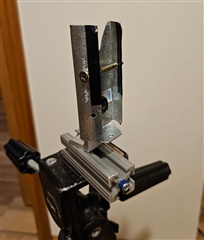
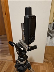
    The mount I knocked up for the 66i fits a standard 5/8” thread antenna mount on my test point (or can free stand over a ground point) and positions the helix within 1cm of the mount base center and +0.17m vertical. It’s not known for sure where the antenna phase center is but from what I’ve read elsewhere it’s assumed to be within the helix.

  • Nice hardware store creation.  I like the metal "skirt" (to minimize signal reflections?)  My version included some 80/20 material I had lying around, but an angle bracket could be used as well.  The screw across the modified fence hanger act as a camp and requires little screw force to secure.  The screw at the end of the aluminum extrusion is positioned directly below the Garmin antenna where a plumb line can be hung.

  • No, despite appearances the skirt isn't anything exotic. Just a simple way of self supporting directly on the ground over a mark without a tripod.

    You are on the right track though; geodetic antennas are made very wide to integrate specialized ground planes or choke rings that reduce multipath from below or low angles. Obviously impractical for a handheld and a reason you will get more noise in these files.